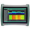


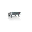
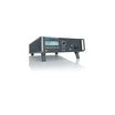
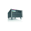


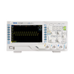
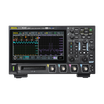
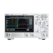


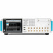


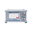


CAMPAIGN - MSO44B 1 GHz Oscilloscope + 4-STARTER-PER
Use our chat for technical support or contact us via +45 31 33 18 19 or salg@GOmeasure.dk
- Analog Bandwidth - 1 GHz
- Analog Channels - 4
- Digital Channels - Up to 32 (Optional)
- Sample Rate - 6.25 GS/s
- Record Length - 31.25 M to 62.5 M
- Included decode and trigger on I2C, SPI, RS232/422/485/UART bus activity.
- Includes an integrated arbitrary/function generator.
%0ASample%20Rate%20-%206.25%20GS/s%0ARecord%20Length%20-%2031.25%20M%20to%2062.5%20M%0AIncluded%20decode%20and%20trigger%20on%20I2C,%20SPI,%20RS232/422/485...
)
Discover the possibilities
More information
Description
What’s new in the 4 Series B
- Faster processor
- > 2X more responsive UI
- > 1.5X faster data transfers
- Faster analysis and serial decoding
- New display with greater contrast and viewing angle
- Two USB 3.1 host ports
- Fast e*Scope browser-based remote access
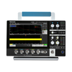
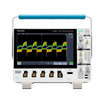
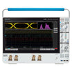
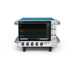
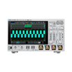
Big HD display and award-winning user interface
With the same made-for-touch user interface technology as the award-winning 5 Series in a compact package, the 4 Series B MSO sets a new expectation of how a scope should work.
- 13.3-inch high-contrast HD display
- 6.1-inch (15.5 cm) deep bench-friendly footprint
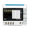
Precise measurements and up to 6 super-flexible channels
- Fine signal detail and accurate measurements on all channels
- 12-bit vertical resolution (16-bit in high res mode)
- 6.25 GS/s on all analog and digital channels
- Up to 62.5 Mpoints record length
- Any channel can show a waveform, RF spectrum, or both
- Any input can be used to view eight digital channels by connecting a logic probe
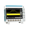
Outstanding analysis
- Discover the capability the 4 Series B can bring to your bench
- Broad range of smart TekVPI probes
- Multi-channel spectrum analysis
- Up to 48 digital logic inputs
- Over 25 available serial protocols
- Built-in arbitrary/function generator
- AC/DC power supply measurements
- Automated double pulse testing
- 3-Phase power analysis
- Field upgradeable -- get the tools you need now or add them later, without having to return the instrument
For more information: Tektronix
Specifications
Documents
Datasheet:
Options
Video
New 4 Series B MSO Oscilloscope Overview
This video provides an overview of the new 4 Series B MSO oscilloscope, highlighting the new faster processor, accurate and precise measurements, and the award-winning user interface.
4 Series B MSO - Outstanding Measurement Performance
The 4 Series B MSO offers powerful measurement and debugging tools. Watch this video to learn about visual triggers, segmented memory, 12 to 16-bit vertical resolution, automated measurements, plots, and statistical tools.
4 Series B MSO - Waveform Display and Controls
This video will give you a taste of the 4 Series B MSO's award-winning user interface, integrating an HD touchscreen display with traditional knobs and buttons. By the end of this video you will know how to use the 4 Series.
4 Series B MSO - Probes, Protocols, Spectrum Analysis, Power Analysis and More
The 4 Series B MSO is a versatile addition to your bench, addressing scores of signal types and applications. This video touches on available probes, RF spectrum analysis, mixed signal analysis, serial protocol decoding, signal generation, power supply measurements, and 3-phase power measurements.
Exploring the Integrated Arbitrary/Function Generator on an Oscilloscope
Having an arbitrary/function generator built into your oscilloscope is useful and convenient. Learn about the AFG outputs available in 2, 4, 5, and 6 Series MSOs.
Logic and Mixed Signal Analysis with a Tektronix Oscilloscope
Built-in logic analysis on mixed signal oscilloscopes expand visibility into digital systems. This video briefly overviews logic probe, settings, triggering, and searches.
Advanced Power Supply Measurements and Analysis with Tektronix Oscilloscopes
Learn how the Advanced Power Supply Measurements and Analysis package for Tektronix oscilloscopes simplifies analysis of power conversion systems with automated power quality, harmonics, switching loss, inductor, efficiency, and stability measurements.
Accurate Oscilloscope Measurement on 3-phase PWM Systems
Making measurements on the PWM (Pulse Width Modulation) outputs of inverters and motor drives is challenging. Learn about automated 3-phase power measurement packages on 4, 5, and 6 Series B MSO oscilloscopes that deliver consistent, accurate results.
CAN Bus Decoding and Triggering on an Oscilloscope
This video covers the basics of CAN bus decoding on Tektronix oscilloscopes as well as the setups for decoding, triggering, and searching for specific values or conditions.
I2C Bus Decoding and Triggering with an Oscilloscope
This video covers the basics of I2C bus decoding on Tektronix oscilloscopes as well as the setups for decoding, triggering, and searching for specific values or conditions.
SPI Bus Decoding and Triggering with an Oscilloscope
This video covers the basics of SPI bus decoding on Tektronix oscilloscopes as well as the setups for decoding, triggering, and searching for specific values or conditions.
Capturing a Clock Frequency Glitch with RF vs Time Trigger
See how an edge trigger on the RF Frequency Deviation vs Time trace isolates and captures a short duration transient in the frequency of a clock signal. The Spectrum View capability on the 4, 5 and 6 Series MSO oscilloscopes can perform edge, pulse width and time-out triggers on RF vs Time waveforms.
Triggering on an ASK (Amplitude Shift-Keying) Signal with Spectrum View
Watch this short demo of RF vs Time hardware trigger to see how an ASK (Amplitude Shift-Keying) signal changes over time. The Spectrum View capability on the 4, 5 and 6 Series MSO oscilloscopes can perform edge, pulse width and time-out triggers on RF vs Time waveforms.
Low amplitude RF emission analysis with RF vs Time Triggering
See how the RF vs Time hardware triggering capability (Spectrum View) on the 4, 5, and 6 Series MSO oscilloscopes can capture a low amplitude RF emission. This video focuses on the low amplitude RF emission from a car’s key fob using the Magnitude vs Time and Frequency vs Time triggers.
Spread Spectrum Clock Analysis with RF vs Time Triggering
See how to stabilize a hardware trigger on the up-down chirp pattern of a spread spectrum clock using a Frequency Deviation vs. Time trigger. The Spectrum View capability on the 4, 5 and 6 Series MSO oscilloscopes can perform edge, pulse width and time-out triggers on RF vs Time waveforms.
Finding Root Cause of EMI Signals with Spectrum View
See how to track down the source of transient RF/EMI emissions with Spectrum View and the RF vs Time triggering capabilities. Clearly determine which PCB signals are causing EMI emissions so that you can pass compliance testing quicker and easier. The Spectrum View capability on the 4, 5 and 6 Series MSO oscilloscopes can perform edge, pulse width and time-out triggers on RF vs Time waveforms.
Boosting the Waveform Update Rate Using Fast Acquisition Mode on the 4 Series MSO
See how different trigger types enable debugging of errant signals much faster and simpler.
What’s new in the 4 Series B
- Faster processor
- > 2X more responsive UI
- > 1.5X faster data transfers
- Faster analysis and serial decoding
- New display with greater contrast and viewing angle
- Two USB 3.1 host ports
- Fast e*Scope browser-based remote access
Big HD display and award-winning user interface
With the same made-for-touch user interface technology as the award-winning 5 Series in a compact package, the 4 Series B MSO sets a new expectation of how a scope should work.
- 13.3-inch high-contrast HD display
- 6.1-inch (15.5 cm) deep bench-friendly footprint
Precise measurements and up to 6 super-flexible channels
- Fine signal detail and accurate measurements on all channels
- 12-bit vertical resolution (16-bit in high res mode)
- 6.25 GS/s on all analog and digital channels
- Up to 62.5 Mpoints record length
- Any channel can show a waveform, RF spectrum, or both
- Any input can be used to view eight digital channels by connecting a logic probe
Outstanding analysis
- Discover the capability the 4 Series B can bring to your bench
- Broad range of smart TekVPI probes
- Multi-channel spectrum analysis
- Up to 48 digital logic inputs
- Over 25 available serial protocols
- Built-in arbitrary/function generator
- AC/DC power supply measurements
- Automated double pulse testing
- 3-Phase power analysis
- Field upgradeable -- get the tools you need now or add them later, without having to return the instrument
For more information: Tektronix
Datasheet:
New 4 Series B MSO Oscilloscope Overview
This video provides an overview of the new 4 Series B MSO oscilloscope, highlighting the new faster processor, accurate and precise measurements, and the award-winning user interface.
4 Series B MSO - Outstanding Measurement Performance
The 4 Series B MSO offers powerful measurement and debugging tools. Watch this video to learn about visual triggers, segmented memory, 12 to 16-bit vertical resolution, automated measurements, plots, and statistical tools.
4 Series B MSO - Waveform Display and Controls
This video will give you a taste of the 4 Series B MSO's award-winning user interface, integrating an HD touchscreen display with traditional knobs and buttons. By the end of this video you will know how to use the 4 Series.
4 Series B MSO - Probes, Protocols, Spectrum Analysis, Power Analysis and More
The 4 Series B MSO is a versatile addition to your bench, addressing scores of signal types and applications. This video touches on available probes, RF spectrum analysis, mixed signal analysis, serial protocol decoding, signal generation, power supply measurements, and 3-phase power measurements.
Exploring the Integrated Arbitrary/Function Generator on an Oscilloscope
Having an arbitrary/function generator built into your oscilloscope is useful and convenient. Learn about the AFG outputs available in 2, 4, 5, and 6 Series MSOs.
Logic and Mixed Signal Analysis with a Tektronix Oscilloscope
Built-in logic analysis on mixed signal oscilloscopes expand visibility into digital systems. This video briefly overviews logic probe, settings, triggering, and searches.
Advanced Power Supply Measurements and Analysis with Tektronix Oscilloscopes
Learn how the Advanced Power Supply Measurements and Analysis package for Tektronix oscilloscopes simplifies analysis of power conversion systems with automated power quality, harmonics, switching loss, inductor, efficiency, and stability measurements.
Accurate Oscilloscope Measurement on 3-phase PWM Systems
Making measurements on the PWM (Pulse Width Modulation) outputs of inverters and motor drives is challenging. Learn about automated 3-phase power measurement packages on 4, 5, and 6 Series B MSO oscilloscopes that deliver consistent, accurate results.
CAN Bus Decoding and Triggering on an Oscilloscope
This video covers the basics of CAN bus decoding on Tektronix oscilloscopes as well as the setups for decoding, triggering, and searching for specific values or conditions.
I2C Bus Decoding and Triggering with an Oscilloscope
This video covers the basics of I2C bus decoding on Tektronix oscilloscopes as well as the setups for decoding, triggering, and searching for specific values or conditions.
SPI Bus Decoding and Triggering with an Oscilloscope
This video covers the basics of SPI bus decoding on Tektronix oscilloscopes as well as the setups for decoding, triggering, and searching for specific values or conditions.
Capturing a Clock Frequency Glitch with RF vs Time Trigger
See how an edge trigger on the RF Frequency Deviation vs Time trace isolates and captures a short duration transient in the frequency of a clock signal. The Spectrum View capability on the 4, 5 and 6 Series MSO oscilloscopes can perform edge, pulse width and time-out triggers on RF vs Time waveforms.
Triggering on an ASK (Amplitude Shift-Keying) Signal with Spectrum View
Watch this short demo of RF vs Time hardware trigger to see how an ASK (Amplitude Shift-Keying) signal changes over time. The Spectrum View capability on the 4, 5 and 6 Series MSO oscilloscopes can perform edge, pulse width and time-out triggers on RF vs Time waveforms.
Low amplitude RF emission analysis with RF vs Time Triggering
See how the RF vs Time hardware triggering capability (Spectrum View) on the 4, 5, and 6 Series MSO oscilloscopes can capture a low amplitude RF emission. This video focuses on the low amplitude RF emission from a car’s key fob using the Magnitude vs Time and Frequency vs Time triggers.
Spread Spectrum Clock Analysis with RF vs Time Triggering
See how to stabilize a hardware trigger on the up-down chirp pattern of a spread spectrum clock using a Frequency Deviation vs. Time trigger. The Spectrum View capability on the 4, 5 and 6 Series MSO oscilloscopes can perform edge, pulse width and time-out triggers on RF vs Time waveforms.
Finding Root Cause of EMI Signals with Spectrum View
See how to track down the source of transient RF/EMI emissions with Spectrum View and the RF vs Time triggering capabilities. Clearly determine which PCB signals are causing EMI emissions so that you can pass compliance testing quicker and easier. The Spectrum View capability on the 4, 5 and 6 Series MSO oscilloscopes can perform edge, pulse width and time-out triggers on RF vs Time waveforms.
Boosting the Waveform Update Rate Using Fast Acquisition Mode on the 4 Series MSO
See how different trigger types enable debugging of errant signals much faster and simpler.