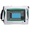
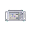

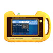
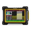
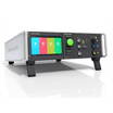

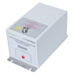

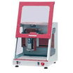
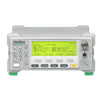


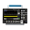
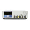

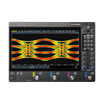
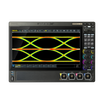
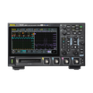

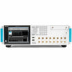
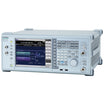
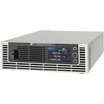

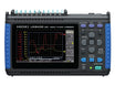

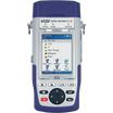
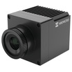
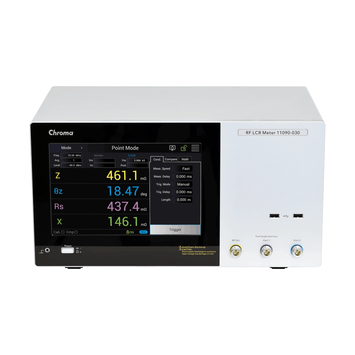
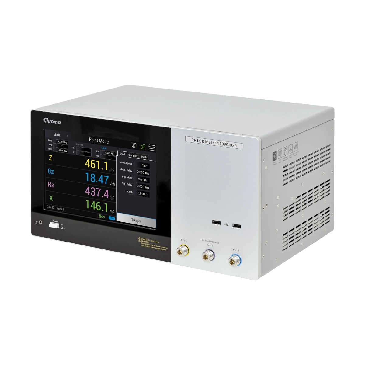
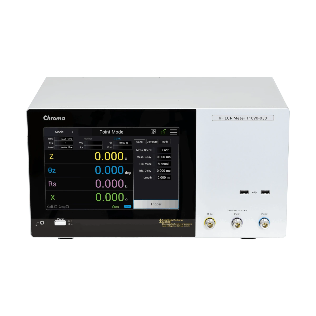
Chroma 11090-030 RF LCR Meter
Use our chat for technical support or contact us via +45 31 33 18 19 or salg@GOmeasure.dk
- Measurement parameters: Z, θz, Y, θy, R, X, G, B, Ls, Lp, Cs, Cp, Rs, Rp, D, Q
- Test frequencies: 100kHz~300MHz
- Measurement range: 100mΩ~5kΩ
- Measurement speed: 0.5/0.9/2.1/3.7 (ms)
- Basic accuracy: ± 0.8% % (typical ± 0.45%)
- Test signal: -40~1(dBm)
- Measurement modes: Point/List
- Test signal (Vm, lm) monitoring function
- Comparator and sorting (13 bins) functions
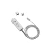
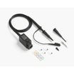
- Contact Check (Rdc 0.1Ω~100Ω @ 1mA max)
- Open/short circuit correction and load compensation functions
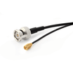
- Standard interfaces: Handler, RS-232C, GPIB, LAN, USB, USB (USBTMC)
%0ABasic%20accuracy:%20...
)
Discover the possibilities
More information
Description
Chroma 11090-030 RF LCR Meter provides a high-frequency measurement and evaluation solution for passive components such as SMD chip inductors and RF filters. With a testing frequency of up to 300MHz, this instrument not only meets the increasing demand for nominal frequency testing of components like POL or small DC-DC converters, but also addresses quality anomalies that can only be detected at ultra-high frequencies. Additionally, it can fulfill common 100MHz impedance testing needs for components like EMI filters and ferrite beads.
This solution covers measurement parameters such as Z, θz, Y, θy, R, X, G, B, Ls, Lp, Cs, Cp, Rs, Rp, D, Q and other primary and secondary parameters required for testing various passive components. The wide test frequency range of 100kHz to 300MHz, using RF current-voltage conversion technology, provides a broader impedance measurement range than network analyzers and a higher frequency measurement range than auto balancing bridge technology. This makes it suitable for analyzing passive component characteristics at different frequencies by R&D and quality assurance units. Furthermore, the instrument’s ultra-low noise, low harmonic distortion signal generator delivers a high quality measurement signal, enhancing the accuracy of impedance testing.
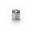
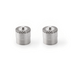
The 11090-030 has a basic measurement accuracy of 0.8%, ensuring highly stable and reliable measurement results. The rapid 0.5ms measurement speed significantly increases production efficiency when employed in an automated environment. The SMD test fixture is compatible with various kinds of small sized SMDs and adopts an improved push down actuation method, which can rotate 90 degrees and requires only three steps to change the DUT (actual testing takes about 40 seconds). This accelerates the speed of test by reducing time spent on changing differently sized DUTs and eliminating the need for repeated reassembly of device guides, which also reduces wear and maintenance costs.
Through its comprehensive design and powerful functional enhancements, Chroma 11090-030 offers a complete test solution for product characterization, rapid testing in automated production lines, and various incoming and outgoing inspection applications
Features
- Wide range of test frequencies: 100kHz~300MHz
- Fast measurement speed: 0.5 (ms)
- Various functions:
Calibration/compensation status guidance - Contact check for magnetic components through Rdc
- Multi-parameter comparison and bin-sorting
- Multi-point (~401 points) test and curve drawing
- Clear and guided operation
- Various functions:
- Fast-operating SMD test fixture (patent TW M621845 / CN 216013502U)
Applications:
- SMD inductors (molded inductors/multilayer inductors/beads, etc.)
- EMI-filter
- Other passive components
Up to 300MHZ Testing Frequency
High-frequency small power inductors are mostly of the metal molded type. However, anomalies such as ① poor original magnetic material (large metal powder/faulty iron oxide film), ② partial oxide film damage after impulse winding test, or ③ coil enamel insulation damage leading to direct contact with the magnetic material, can all cause a reduction in quality factor (Q), making them susceptible to overheating during subsequent use. When testing for these three types of anomalies under nominal frequency test conditions, the Q-value is significantly influenced by the probe’s contact resistance due to the low impedance of the inductor. By increasing the testing frequency to raise impedance and reduce the impact of the probe’s contact resistance, the detection rate of abnormalities in the magnetic material and wire insulation can be enhanced. This method is widely adopted in the inductor industry.
Most magnetic metal powders used for inductors have their surfaces treated with an oxide film to reduce eddy current losses caused by high-frequency AC, in turn expanding the usable frequency range while reducing power losses and heat. Although users cannot determine powder size and the integrity of the oxide film compression molding and sintering from their outside appearance, high-frequency testing is effective in discerning these characteristics.
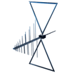
Figure 1 shows a high-frequency equivalent circuit for an inductor and the formula for the relationship between inductance (Ls) and Q. It is common industry practice to use an Ls value near the self-resonant frequency (SRF) to detect the quality anomalies described earlier. This is essentially a check of whether the Q-value is low while avoiding the impact of contact resistance. Normal inductors have higher Ls close to their SRF because of stray capacitance, while defective products exhibit lower Ls due to significantly reduced Q-values resulting from excessive loss. Chroma 11090-030's wide 100kHz-300MHz testing range meets the dual testing requirements of rated Ls/Q and high-frequency Ls, satisfying the production needs of such inductors. The tester is also suitable for R&D, quality assurance, and general inductor use cases.
Impedance Measurement and Accuracy
Chroma 11090-030 uses the RF-IV measurement method to measure the voltage and current of the device under test (DUT). Compared with conventional network analyzers, the 11090-030 provides more accurate measurements over a wider impedance range (100mΩ~5kΩ), and is capable of measuring inductance values as small as a few nH. In addition, the 11090-030’s wide frequency range (100kHz to 300MHz) caters to DUTs with dual-frequency test requirements that involve hundreds of kHz as well as MHz levels, eliminating the need to deploy separate test equipment in multiple sets or stations and thereby reducing procurement costs.
Function Features
Calibration/Compensation Guidance Function
Accurate calibration (OPEN/SHORT/LOAD) is crucial in RF LCR measurements. Any errors or omissions in the calibration process can lead to inaccurate results. The 11090-030 features a guided calibration/compensation method that eliminates errors in this complex process. The user-friendly guided calibration procedure reduces the risk of missing steps, provides graphical guidance to minimize errors in selecting standard components, and offers corresponding displays for users who have completed the calibration process.
Contact Check for Magnetic Components Using Rdc
SMD components subjected to RF LCR measurements are generally very small, and determining the quality of contact with test fixtures or in automated tests is challenging. The 11090-030 provides a contact check function for magnetic components using direct current resistance Rdc. Since Rdc is a parameter that doesn't require calibration and offers the most direct way to confirm contact for magnetic components (inductors, EMI filters, beads), this function helps to achieve more accurate sorting of defects on the production line and enhances the efficiency of classifying faulty products.
Multi-parameter Comparison and Classification Function
RF testing involves determining the quality of goods or defects in different frequency domains, which might vary due to different parameters, absolute values, percentages, main and secondary parameter focus, and high/low judgment methods. The Chroma 11090-030 offers a highly flexible table format with up to 13 bins, each having four limit values. Conditions like frequency and measurement parameters can be independently set for each column, enabling the 11090-030 to meet diverse sorting requirements, including different parameters under different measurement frequencies.
Multi-point Testing and Curve Drawing with Up to 401 Points
RF components often require analyzing parameter frequency response changes across multiple frequency domains. The 11090-030's multi-point measurement function allows setting up to 401 points, providing users with detailed and precise measurement values. It offers the choice of multi-point lists and characteristic curve plotting, which helps production test and analysis personnel to gain a rapid understanding of component frequency characteristics.
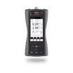
Clear and Guided Operation
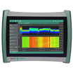
Utilizing a touch-enabled, full-color, high-resolution LCD display, the 11090-030 clearly shows multiple parameter test results and settings, comparison and sorting results, and deviations from reference values. Easily identifiable icons indicate instrument status and provide guidance for quick operations, providing users with usability as well as comprehensive information.
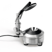
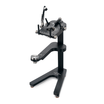
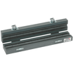
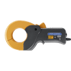
Fast-Operating SMD Test Fixture
Patent TW M621845 / CN 216013502U
SMD components come in diverse and minuscule sizes, requiring extremely precise special materials for positioning. However, changing sizes often requires reassembling the device guides, which is not only time-consuming but also risks damaging expensive components and shims. The SMD test fixture is compatible with various kinds of small-sized SMDs and adopts an improved push-down actuation method, which can rotate 90 degrees and requires only three steps to change the DUT (actual testing takes about 40 seconds). This accelerates the speed of test by reducing time spent on changing differently sized DUTs and eliminating the need for repeated reassembly of s device guides, which also reduces wear and subsequent maintenance costs.
Transmission Interface
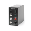
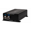
The 11090-030 offers a complete range of interfaces, which includes interfaces for setting measurement conditions, triggering measurement actions, determining measurement results and collecting measurement data. LAN, GPIB, USB (B-Type), RS-232 and USB (A-Type) storage interface are all included. Through the Handler interface, measurements can be triggered and the judgment results can be exported.
Specifications
Documents
Options
Video
Chroma 11090-030 RF LCR Meter provides a high-frequency measurement and evaluation solution for passive components such as SMD chip inductors and RF filters. With a testing frequency of up to 300MHz, this instrument not only meets the increasing demand for nominal frequency testing of components like POL or small DC-DC converters, but also addresses quality anomalies that can only be detected at ultra-high frequencies. Additionally, it can fulfill common 100MHz impedance testing needs for components like EMI filters and ferrite beads.
This solution covers measurement parameters such as Z, θz, Y, θy, R, X, G, B, Ls, Lp, Cs, Cp, Rs, Rp, D, Q and other primary and secondary parameters required for testing various passive components. The wide test frequency range of 100kHz to 300MHz, using RF current-voltage conversion technology, provides a broader impedance measurement range than network analyzers and a higher frequency measurement range than auto balancing bridge technology. This makes it suitable for analyzing passive component characteristics at different frequencies by R&D and quality assurance units. Furthermore, the instrument’s ultra-low noise, low harmonic distortion signal generator delivers a high quality measurement signal, enhancing the accuracy of impedance testing.
The 11090-030 has a basic measurement accuracy of 0.8%, ensuring highly stable and reliable measurement results. The rapid 0.5ms measurement speed significantly increases production efficiency when employed in an automated environment. The SMD test fixture is compatible with various kinds of small sized SMDs and adopts an improved push down actuation method, which can rotate 90 degrees and requires only three steps to change the DUT (actual testing takes about 40 seconds). This accelerates the speed of test by reducing time spent on changing differently sized DUTs and eliminating the need for repeated reassembly of device guides, which also reduces wear and maintenance costs.
Through its comprehensive design and powerful functional enhancements, Chroma 11090-030 offers a complete test solution for product characterization, rapid testing in automated production lines, and various incoming and outgoing inspection applications
Features
- Wide range of test frequencies: 100kHz~300MHz
- Fast measurement speed: 0.5 (ms)
- Various functions:
Calibration/compensation status guidance - Contact check for magnetic components through Rdc
- Multi-parameter comparison and bin-sorting
- Multi-point (~401 points) test and curve drawing
- Clear and guided operation
- Various functions:
- Fast-operating SMD test fixture (patent TW M621845 / CN 216013502U)
Applications:
- SMD inductors (molded inductors/multilayer inductors/beads, etc.)
- EMI-filter
- Other passive components
Up to 300MHZ Testing Frequency
High-frequency small power inductors are mostly of the metal molded type. However, anomalies such as ① poor original magnetic material (large metal powder/faulty iron oxide film), ② partial oxide film damage after impulse winding test, or ③ coil enamel insulation damage leading to direct contact with the magnetic material, can all cause a reduction in quality factor (Q), making them susceptible to overheating during subsequent use. When testing for these three types of anomalies under nominal frequency test conditions, the Q-value is significantly influenced by the probe’s contact resistance due to the low impedance of the inductor. By increasing the testing frequency to raise impedance and reduce the impact of the probe’s contact resistance, the detection rate of abnormalities in the magnetic material and wire insulation can be enhanced. This method is widely adopted in the inductor industry.
Most magnetic metal powders used for inductors have their surfaces treated with an oxide film to reduce eddy current losses caused by high-frequency AC, in turn expanding the usable frequency range while reducing power losses and heat. Although users cannot determine powder size and the integrity of the oxide film compression molding and sintering from their outside appearance, high-frequency testing is effective in discerning these characteristics.
Figure 1 shows a high-frequency equivalent circuit for an inductor and the formula for the relationship between inductance (Ls) and Q. It is common industry practice to use an Ls value near the self-resonant frequency (SRF) to detect the quality anomalies described earlier. This is essentially a check of whether the Q-value is low while avoiding the impact of contact resistance. Normal inductors have higher Ls close to their SRF because of stray capacitance, while defective products exhibit lower Ls due to significantly reduced Q-values resulting from excessive loss. Chroma 11090-030's wide 100kHz-300MHz testing range meets the dual testing requirements of rated Ls/Q and high-frequency Ls, satisfying the production needs of such inductors. The tester is also suitable for R&D, quality assurance, and general inductor use cases.
Impedance Measurement and Accuracy
Chroma 11090-030 uses the RF-IV measurement method to measure the voltage and current of the device under test (DUT). Compared with conventional network analyzers, the 11090-030 provides more accurate measurements over a wider impedance range (100mΩ~5kΩ), and is capable of measuring inductance values as small as a few nH. In addition, the 11090-030’s wide frequency range (100kHz to 300MHz) caters to DUTs with dual-frequency test requirements that involve hundreds of kHz as well as MHz levels, eliminating the need to deploy separate test equipment in multiple sets or stations and thereby reducing procurement costs.
Function Features
Calibration/Compensation Guidance Function
Accurate calibration (OPEN/SHORT/LOAD) is crucial in RF LCR measurements. Any errors or omissions in the calibration process can lead to inaccurate results. The 11090-030 features a guided calibration/compensation method that eliminates errors in this complex process. The user-friendly guided calibration procedure reduces the risk of missing steps, provides graphical guidance to minimize errors in selecting standard components, and offers corresponding displays for users who have completed the calibration process.
Contact Check for Magnetic Components Using Rdc
SMD components subjected to RF LCR measurements are generally very small, and determining the quality of contact with test fixtures or in automated tests is challenging. The 11090-030 provides a contact check function for magnetic components using direct current resistance Rdc. Since Rdc is a parameter that doesn't require calibration and offers the most direct way to confirm contact for magnetic components (inductors, EMI filters, beads), this function helps to achieve more accurate sorting of defects on the production line and enhances the efficiency of classifying faulty products.
Multi-parameter Comparison and Classification Function
RF testing involves determining the quality of goods or defects in different frequency domains, which might vary due to different parameters, absolute values, percentages, main and secondary parameter focus, and high/low judgment methods. The Chroma 11090-030 offers a highly flexible table format with up to 13 bins, each having four limit values. Conditions like frequency and measurement parameters can be independently set for each column, enabling the 11090-030 to meet diverse sorting requirements, including different parameters under different measurement frequencies.
Multi-point Testing and Curve Drawing with Up to 401 Points
RF components often require analyzing parameter frequency response changes across multiple frequency domains. The 11090-030's multi-point measurement function allows setting up to 401 points, providing users with detailed and precise measurement values. It offers the choice of multi-point lists and characteristic curve plotting, which helps production test and analysis personnel to gain a rapid understanding of component frequency characteristics.
Clear and Guided Operation
Utilizing a touch-enabled, full-color, high-resolution LCD display, the 11090-030 clearly shows multiple parameter test results and settings, comparison and sorting results, and deviations from reference values. Easily identifiable icons indicate instrument status and provide guidance for quick operations, providing users with usability as well as comprehensive information.
Fast-Operating SMD Test Fixture
Patent TW M621845 / CN 216013502U
SMD components come in diverse and minuscule sizes, requiring extremely precise special materials for positioning. However, changing sizes often requires reassembling the device guides, which is not only time-consuming but also risks damaging expensive components and shims. The SMD test fixture is compatible with various kinds of small-sized SMDs and adopts an improved push-down actuation method, which can rotate 90 degrees and requires only three steps to change the DUT (actual testing takes about 40 seconds). This accelerates the speed of test by reducing time spent on changing differently sized DUTs and eliminating the need for repeated reassembly of s device guides, which also reduces wear and subsequent maintenance costs.
Transmission Interface
The 11090-030 offers a complete range of interfaces, which includes interfaces for setting measurement conditions, triggering measurement actions, determining measurement results and collecting measurement data. LAN, GPIB, USB (B-Type), RS-232 and USB (A-Type) storage interface are all included. Through the Handler interface, measurements can be triggered and the judgment results can be exported.