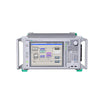
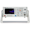
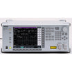
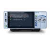

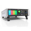

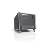


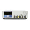

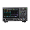

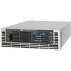
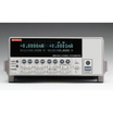


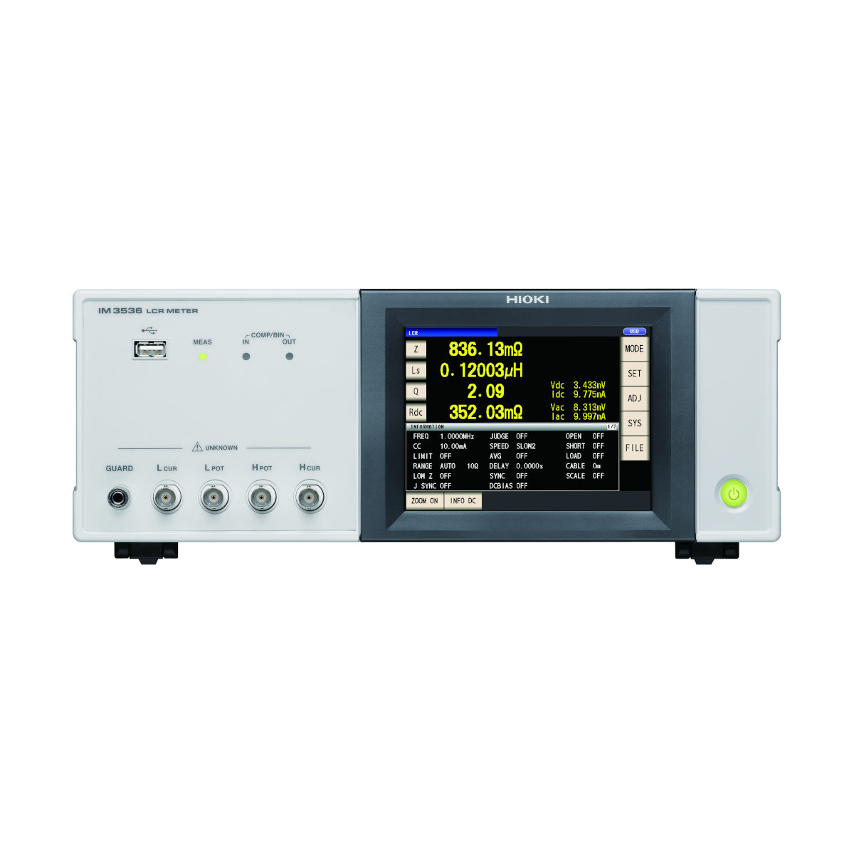
Hioki IM3536 LCR Meter
Use our chat for technical support or contact us via +45 31 33 18 19 or salg@GOmeasure.dk
General-Purpose LCR Meters with Measurement Frequency from DC, 4 Hz to 8 MHz
Discover the possibilities
More information
Description
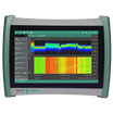
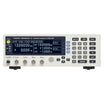
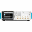
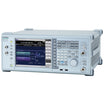
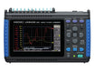
Hioki IM3536 LCR Meter
Hioki LCR Meters and Impedance Analyzers range from 1mHz to 3GHz devices to suit a wide range of applications in the testing of electronic components. The IM3536 raises the industry standard for general-purpose LCR meters by offering a wide DC and 4Hz to 8MHz (up to 10MHz special order available) testing frequency while delivering 0.05% accuracy, ideal for evaluating the characteristics of next generation electronic components, including power supply inductors thanks to the instrument’s maximum measurement frequency of 8MHz. (up to 10MHz special order available)
Key Features
- DC, 4 Hz to 8 MHz measurement frequency
- High-speed measurement of 1 ms (fastest time)
- High-precision measurement of ±0.05% rdg. (representative value)
- Guaranteed accuracy range from 1 mΩ, low-impedance measurement with unmatched repeatability
- DC bias function: Measure under conditions simulating actual use or in accordance with industry standards
- Exceptional specifications and cost-performance for a wide range of applications, from R&D to production lines
*1: Can be customized up to 10 MHz (special order available). Please contact your authorized Hioki distributor or reseller for more information.
Specifications
Basic specifications
Accuracy guaranteed: 1 year
| Measurement modes | LCR (Measurement with single condition), Continuous testing (Continuous measurement under saved conditions) | |||||
|---|---|---|---|---|---|---|
| Measurement parameters | Z, Y, θ, X, G, B, Q, Rdc (DC resistance), Rs (ESR), Rp, Ls, Lp, Cs, Cp, D (tanδ), σ, ε | |||||
| Measurement range | 100 mΩ to 100 MΩ, 10 ranges (All parameters are determined according to Z) | |||||
| Display range | Z: 0.00 m to 9.99999 GΩ, Y: 0.000 n to 9.99999 GS, θ: ± (0.000° to 180.000°), Q: ± (0.00 to 9999.99), Rdc: ± (0.00 m to 9.99999 GΩ), D: ± (0.00000 to 9.99999), Δ%: ± (0.000 % to 999.999 %), or other | |||||
| Basic accuracy | Z ±0.05% rdg. θ: ±0.03° (representative value, Measurable range: 1 mΩ to 200 MΩ) | |||||
| Measurement frequency | 4 Hz to 8 MHz (5 digits setting resolution, minimum resolution 10 mHz) | |||||
| Measurement signal level | [Normal mode: V mode/CV mode] 4 Hz to 1.0000 MHz: 10 mV to 5 Vrms (maximum 50 mArms) 1.0001 MHz to 8 MHz: 10 mV to 1 Vrms (maximum 10mArms) [Low impedance high accuracy mode: V mode/CV mode] 4 Hz to 1.0000 MHz: 10 mV to 1 Vrms (maximum 100 mArms) [Normal mode: CC mode] 4 Hz to 1.0000 MHz: 10 μA to 50 mArms (maximum 5 Vrms) 1.0001 MHz to 8 MHz: 10 μA to 10 mArms (maximum 1 Vrms) [Low impedance high accuracy mode: CC mode] 4 Hz to 1.0000 MHz: 10 μA to 100 mArms (maximum 1 Vrms) [DC resistance measurement] Measurement signal level: Fixed at 1 V | |||||
| DC bias measurement | Generating range: DC voltage 0 V to 2.50 V (10 mV resolution) In low Z high accuracy mode: 0 V to 1 V (10 mV resolution) | |||||
| Output impedance | Normal mode: 100 Ω, Low impedance high accuracy mode: 10 Ω | |||||
| Display | 5.7-inch color TFT with touch panel | |||||
| Functions | Comparator, BIN measurement (10 categories for 2 measurement parameters), Trigger function, Open/short compensation, Contact check, Panel loading/saving, Memory function | |||||
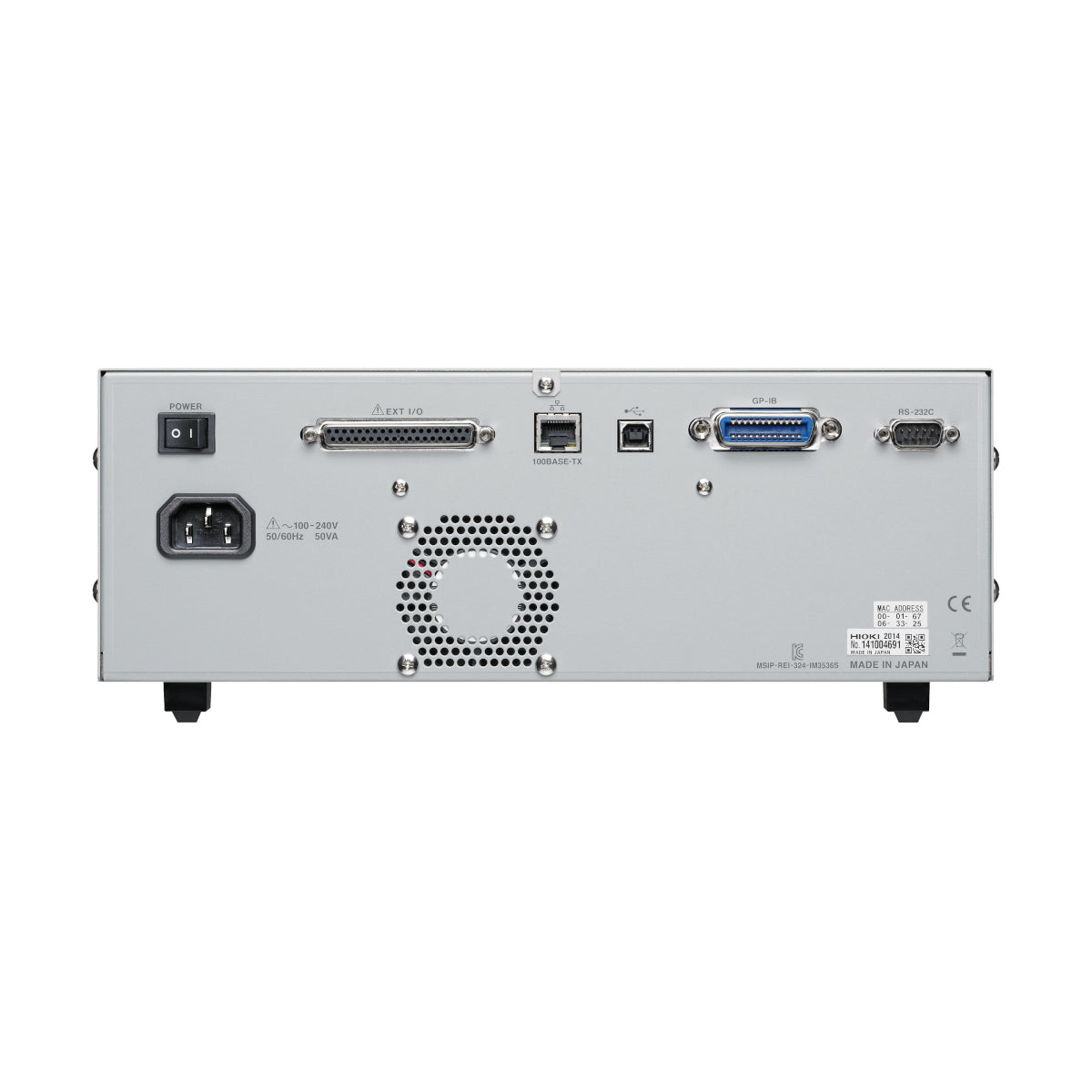
| Interfaces | EXT. I/O( HANDLER) ,USB, USB flash drive, LAN, GP-IB, RS-232C, BCD | |||||
| Power supply | 100 to 240 V AC, 50/60 Hz, 50 VA max. | |||||
| Dimensions and mass | 330 mm (12.99 in) W × 119 mm (4.69 in) H × 230 mm (9.06 in) D, 4.2 kg (148.1 oz) | |||||
| Included accessories | Power cord ×1, Instruction manual ×1, LCR application disc (Communications user manual) ×1 | |||||
Documents
Datasheet
Options
Video
Hioki IM3536 LCR Meter
Hioki LCR Meters and Impedance Analyzers range from 1mHz to 3GHz devices to suit a wide range of applications in the testing of electronic components. The IM3536 raises the industry standard for general-purpose LCR meters by offering a wide DC and 4Hz to 8MHz (up to 10MHz special order available) testing frequency while delivering 0.05% accuracy, ideal for evaluating the characteristics of next generation electronic components, including power supply inductors thanks to the instrument’s maximum measurement frequency of 8MHz. (up to 10MHz special order available)
Key Features
- DC, 4 Hz to 8 MHz measurement frequency
- High-speed measurement of 1 ms (fastest time)
- High-precision measurement of ±0.05% rdg. (representative value)
- Guaranteed accuracy range from 1 mΩ, low-impedance measurement with unmatched repeatability
- DC bias function: Measure under conditions simulating actual use or in accordance with industry standards
- Exceptional specifications and cost-performance for a wide range of applications, from R&D to production lines
*1: Can be customized up to 10 MHz (special order available). Please contact your authorized Hioki distributor or reseller for more information.
Basic specifications
Accuracy guaranteed: 1 year
| Measurement modes | LCR (Measurement with single condition), Continuous testing (Continuous measurement under saved conditions) | |||||
|---|---|---|---|---|---|---|
| Measurement parameters | Z, Y, θ, X, G, B, Q, Rdc (DC resistance), Rs (ESR), Rp, Ls, Lp, Cs, Cp, D (tanδ), σ, ε | |||||
| Measurement range | 100 mΩ to 100 MΩ, 10 ranges (All parameters are determined according to Z) | |||||
| Display range | Z: 0.00 m to 9.99999 GΩ, Y: 0.000 n to 9.99999 GS, θ: ± (0.000° to 180.000°), Q: ± (0.00 to 9999.99), Rdc: ± (0.00 m to 9.99999 GΩ), D: ± (0.00000 to 9.99999), Δ%: ± (0.000 % to 999.999 %), or other | |||||
| Basic accuracy | Z ±0.05% rdg. θ: ±0.03° (representative value, Measurable range: 1 mΩ to 200 MΩ) | |||||
| Measurement frequency | 4 Hz to 8 MHz (5 digits setting resolution, minimum resolution 10 mHz) | |||||
| Measurement signal level | [Normal mode: V mode/CV mode] 4 Hz to 1.0000 MHz: 10 mV to 5 Vrms (maximum 50 mArms) 1.0001 MHz to 8 MHz: 10 mV to 1 Vrms (maximum 10mArms) [Low impedance high accuracy mode: V mode/CV mode] 4 Hz to 1.0000 MHz: 10 mV to 1 Vrms (maximum 100 mArms) [Normal mode: CC mode] 4 Hz to 1.0000 MHz: 10 μA to 50 mArms (maximum 5 Vrms) 1.0001 MHz to 8 MHz: 10 μA to 10 mArms (maximum 1 Vrms) [Low impedance high accuracy mode: CC mode] 4 Hz to 1.0000 MHz: 10 μA to 100 mArms (maximum 1 Vrms) [DC resistance measurement] Measurement signal level: Fixed at 1 V | |||||
| DC bias measurement | Generating range: DC voltage 0 V to 2.50 V (10 mV resolution) In low Z high accuracy mode: 0 V to 1 V (10 mV resolution) | |||||
| Output impedance | Normal mode: 100 Ω, Low impedance high accuracy mode: 10 Ω | |||||
| Display | 5.7-inch color TFT with touch panel | |||||
| Functions | Comparator, BIN measurement (10 categories for 2 measurement parameters), Trigger function, Open/short compensation, Contact check, Panel loading/saving, Memory function | |||||
| Interfaces | EXT. I/O( HANDLER) ,USB, USB flash drive, LAN, GP-IB, RS-232C, BCD | |||||
| Power supply | 100 to 240 V AC, 50/60 Hz, 50 VA max. | |||||
| Dimensions and mass | 330 mm (12.99 in) W × 119 mm (4.69 in) H × 230 mm (9.06 in) D, 4.2 kg (148.1 oz) | |||||
| Included accessories | Power cord ×1, Instruction manual ×1, LCR application disc (Communications user manual) ×1 | |||||