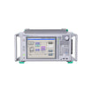


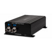
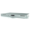

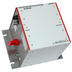
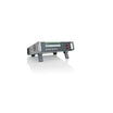


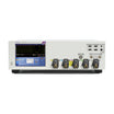


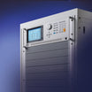


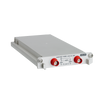


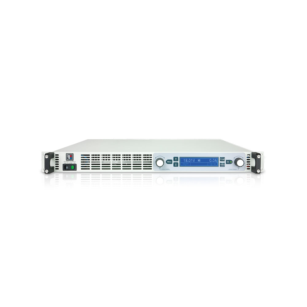
EA PS 9750-06 1U 1500W Lab Power Supply
Use our chat for technical support or contact us via +45 31 33 18 19 or salg@GOmeasure.dk
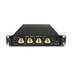
- Housing: 19" rack
- Voltage (U): 750.00
- Current (I) Ampere: 6.00
- Power (P) Watt: 1500.00
:%20750.00%0ACurrent%20(I)%20Ampere:%206.00%0APower%20(P)%20Watt:%201500.00%0A
)
Discover the possibilities
More information
Description
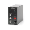
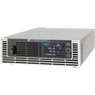
The microprocessor-controlled laboratory power supplies of series EA-PS 9000 1U offer many functions and features in their standard version, making the use of this equipment remarkably easy and most effective. All this comes in a flat design with only 44 mm (1.75”) of height.
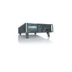
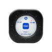
The clearly arranged control panel features two rotary knobs, six pushbuttons and two LEDs. Together with an illuminated, blue LCD display for all values and status it simplifies the use of the device.
Features
- Wide AC supply voltage range: 100...264 V (1500W models), with active PFC
- High efficiency: up to 95%
- Output power ratings: 0...1500 W or 0...3000 W
- Output voltages: 0...80 V up to 0...750 V
- Output currents: 0...6 A up to 0...100 A
- Flexible, power regulated output stage
- Various protection circuits (OVP, OCP, OPP, OTP)
- Control panel with pushbuttons and blue LCD for actual values, set values, status and alarms
- Remote sensing
- Share bus for support of parallel connection
- Galvanically isolated analog and digital (USB, Ethernet) interfaces
- Very low height of only 1U
- Temperature-controlled fans for cooling
- SCPI command set and ModBus RTU support
- LabView VIs and control software for Windows
AC supply
All units are provided with an active Power Factor Correction circuit and models up to 1.5 kW are even suitable for a worldwide operation on a supply from 100 VAC up to 264 VAC.
Both power classes reduce the output power automatically when the input supply is low, so the 1.5 kW models can still provide 1 kW power with an input supply of 100...150 VAC and the 3 kW models can still provide 2.5 kW at 180...207 VAC.
DC output
DC output voltages between 0...80 V and 0...750 V, output currents between 0...6 A and 0...100 A and output power ratings of 0...1500 W or 0...3000 W are available. Current, voltage and power can thus be adjusted continuously between 0% and 100%, no matter if manually or remote-ly controlled (analog or digital).The DC output is located on the rear panel of the devices.
Power
All models are equipped with a flexible autoranging output stage which provides a higher output voltage at lower output current, or a higher output current at lower output voltage, always limited to the adjustable power set val-ue or the rated power. Therefore, a wide range of applications can already be covered by the use of just one unit.
Discharge circuit
Models with a nominal output voltage of 200 V or higher include a discharge circuit for the output capacities. For no load or low load situations, it ensures that the dangerous output voltage can sink to under 60 V DC after the DC output has been switched off. This value is considered as limit for voltages dangerous to human safety.
Protective features
For protection of the equipment connected, it is possible to set an overvoltage protection threshold (OVP), as well as one for overcurrent (OCP) and overpower (OPP).
As soon as one of these thresholds is reached for any reason, the DC output will be immediately shut off and a status signal will be generated on the display and via the interfaces. There is furthermore an overtemperature protection, which will shut off the DC output if the device overheats.
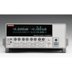
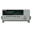
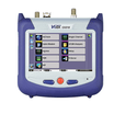
Display and controls
All important information is clearly visualised on a dot matrix display.
With this, information about the actual output values and set values of voltage and current, the actual control state (CV, CC, CP) and other statuses, as well as alarms and settings of the setup menu are clearly displayed.
In order to ease adjusting of values by the rotary knobs, pushing them can switch between decimal positions of a value. All these features contribute to an operator friendliness. With a panel lock feature, the whole panel can be locked in order to protect the equipment and the loads from unintentional misuse.
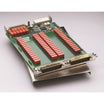
Analog interface
There is a galvanically isolated analog interface terminal, located on the rear of the device. It offers an-alog inputs to set voltage, current and power from 0...100% through control voltages of 0 V...10 V or 0 V...5 V. To monitor the output voltage and current, there are analog outputs with voltage ranges of 0 V...10 V or 0 V...5 V. Also, several inputs and outputs are available for controlling and monitoring the de-vice status.
Digital interfaces
All models feature two galvanically isolated, digital interfaces by default. These are 1x USB and 1x Ether-
net. Both can be used to control and monitor the devices with SCPI language commands or ModBus RTU protocol.
Remote control of a device can be done either by the included software EA Power Control (see page 118)or by a custom application, which is supported by a programming documentation, as well as LabView Virtual Instruments (VIs).
Specifications
Documents
Options
Video
The microprocessor-controlled laboratory power supplies of series EA-PS 9000 1U offer many functions and features in their standard version, making the use of this equipment remarkably easy and most effective. All this comes in a flat design with only 44 mm (1.75”) of height.
The clearly arranged control panel features two rotary knobs, six pushbuttons and two LEDs. Together with an illuminated, blue LCD display for all values and status it simplifies the use of the device.
Features
- Wide AC supply voltage range: 100...264 V (1500W models), with active PFC
- High efficiency: up to 95%
- Output power ratings: 0...1500 W or 0...3000 W
- Output voltages: 0...80 V up to 0...750 V
- Output currents: 0...6 A up to 0...100 A
- Flexible, power regulated output stage
- Various protection circuits (OVP, OCP, OPP, OTP)
- Control panel with pushbuttons and blue LCD for actual values, set values, status and alarms
- Remote sensing
- Share bus for support of parallel connection
- Galvanically isolated analog and digital (USB, Ethernet) interfaces
- Very low height of only 1U
- Temperature-controlled fans for cooling
- SCPI command set and ModBus RTU support
- LabView VIs and control software for Windows
AC supply
All units are provided with an active Power Factor Correction circuit and models up to 1.5 kW are even suitable for a worldwide operation on a supply from 100 VAC up to 264 VAC.
Both power classes reduce the output power automatically when the input supply is low, so the 1.5 kW models can still provide 1 kW power with an input supply of 100...150 VAC and the 3 kW models can still provide 2.5 kW at 180...207 VAC.
DC output
DC output voltages between 0...80 V and 0...750 V, output currents between 0...6 A and 0...100 A and output power ratings of 0...1500 W or 0...3000 W are available. Current, voltage and power can thus be adjusted continuously between 0% and 100%, no matter if manually or remote-ly controlled (analog or digital).The DC output is located on the rear panel of the devices.
Power
All models are equipped with a flexible autoranging output stage which provides a higher output voltage at lower output current, or a higher output current at lower output voltage, always limited to the adjustable power set val-ue or the rated power. Therefore, a wide range of applications can already be covered by the use of just one unit.
Discharge circuit
Models with a nominal output voltage of 200 V or higher include a discharge circuit for the output capacities. For no load or low load situations, it ensures that the dangerous output voltage can sink to under 60 V DC after the DC output has been switched off. This value is considered as limit for voltages dangerous to human safety.
Protective features
For protection of the equipment connected, it is possible to set an overvoltage protection threshold (OVP), as well as one for overcurrent (OCP) and overpower (OPP).
As soon as one of these thresholds is reached for any reason, the DC output will be immediately shut off and a status signal will be generated on the display and via the interfaces. There is furthermore an overtemperature protection, which will shut off the DC output if the device overheats.
Display and controls
All important information is clearly visualised on a dot matrix display.
With this, information about the actual output values and set values of voltage and current, the actual control state (CV, CC, CP) and other statuses, as well as alarms and settings of the setup menu are clearly displayed.
In order to ease adjusting of values by the rotary knobs, pushing them can switch between decimal positions of a value. All these features contribute to an operator friendliness. With a panel lock feature, the whole panel can be locked in order to protect the equipment and the loads from unintentional misuse.
Analog interface
There is a galvanically isolated analog interface terminal, located on the rear of the device. It offers an-alog inputs to set voltage, current and power from 0...100% through control voltages of 0 V...10 V or 0 V...5 V. To monitor the output voltage and current, there are analog outputs with voltage ranges of 0 V...10 V or 0 V...5 V. Also, several inputs and outputs are available for controlling and monitoring the de-vice status.
Digital interfaces
All models feature two galvanically isolated, digital interfaces by default. These are 1x USB and 1x Ether-
net. Both can be used to control and monitor the devices with SCPI language commands or ModBus RTU protocol.
Remote control of a device can be done either by the included software EA Power Control (see page 118)or by a custom application, which is supported by a programming documentation, as well as LabView Virtual Instruments (VIs).