


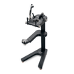


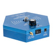
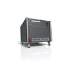


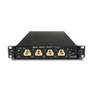


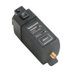


EA-ELM 5200-12 0...320W Electronic Load modul
Brug vores chat til teknisk support eller kontakt os via +45 31 33 18 19 eller salg@GOmeasure.dk
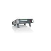
- Bolig: 19" rack
- Spænding (U): 200,00
- Strøm (I) Ampere: 12.00
- Effekt (P) Watt: 320,00
:%20200,00%0AStr%C3%B8m%20(I)%20Ampere:%2012.00%0AEffekt%20(P)%20Watt:%20320,00%0A
)
Opdag mulighederne
Mere information
Beskrivelse
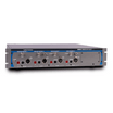
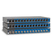
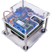
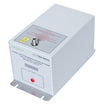
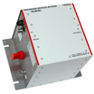
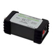
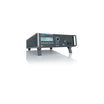
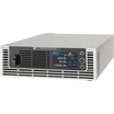
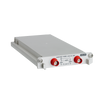
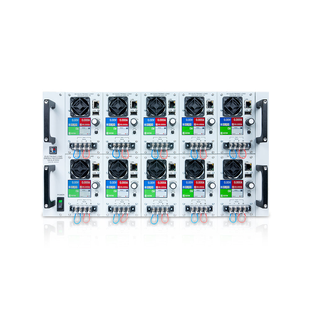
This series EA-ELR 5000 was designed to configure a multi-channel electronic DC load. In a rack for 19” sys-tems, up to ten DC load units with 320 W nominal power each can be installed. The modular units operate separately from each other, but require the rack as it contains the energy recovering DC-AC inverter. The modules are also extendable. Parallel connection on the DC inputs of the module is possible. The load mod-ules come in two voltage variants, 80 V and 200 V, and incorporate the common regulation modes constant voltage (CV), constant current (CC) and constant power (CP).
The energy recovery function inverts the supplied DC energy into a synchronous sine current and feeds it back into the local grid. This reduces the usual heat dissipation to a minimum and saves energy costs at the same time. The color TFT touch panel offers an intuitive kind of manual operation.
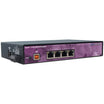
Equipped with an Ethernet port by default, the load units can be easily integrated into a network of LAN devices with a standard LAN switch, which is also available as accessory (Netgear, 1U, 19”). External con-trol is possible via an included Windows software or via custom applications created in LabView or other IDEs. The commonly known communication protocols SCPI and ModBus RTU are supported.
* Modbus TCP only from firmware 2.05
Features:
- Multi-channel DC load
- Energy recovery of the supplied DC energy into the local grid
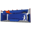
- 19” 6U rack for up to 10 separate load modules
- Input power rating: 320 W per module
- Input voltages: 80 V or 200 V
- Input currents: 12 A or 25 A per module
- Remote sensing
- μController based digital control
- Bilingual TFT touch panel (German/English)
- Sequence generator
- Battery test function
- MPP tracking function
- Ethernet/LAN interface built-in
- SCPI and ModBus RTU/TCP* command set
Power ratings, voltages, currents
There are two load models available. One for max. 80 V DC input voltage and one for max. 200 V. Both mod-els have a max. power of 320 W, while the 80 V model can take up to 25 A and the 200 V can take up to 12 A or current. By installing up to 10 units of these load modules into a single rack it's possible to extend the power to a total of 3200 W.
Construction
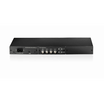
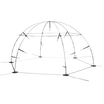
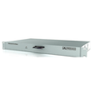
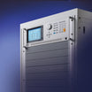
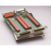
The rack, which is used to hold the load modules is designed in 19“ width and 6U of height, while having an installation depth of 480 mm (18.9”). This makes it ideal for use in 19“ cabinets of various sizes.
Supply
The rack requires to be wired to a main connection with 208 V AC (±10%) and minimum 16 A fusing. The re-covery feature requires to always have sufficient devices on the local power grid to consume the recuper-ated energy.
Energy recovery
The most important feature of these electronic loads is that the AC input, i.e. grid connection, is also used as output for the recov-ery of the supplied DC energy, which will be converted with an effi-ciency of up to 95%. This way of energy recovery helps to lower en-ergy costs and avoids expensive cooling systems, such as required for conventional electronic loads which convert the DC input ener-gy into heat.
Operation of these recovering loads in terms of electricity gener-ation is not intended. Grid protection devices which can supervise the feedback of energy into the public grid are available on the mar-ket for optional installation and are installed to achieve additional safety of persons and equipment, especially when running the so-called isolated operation.
Operation (HMI)
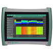
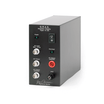
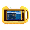
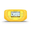
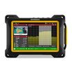
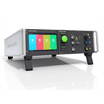
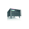
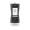
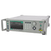
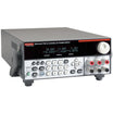
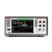
Manual operation is done with a resistive touch panel, two rotary knobs and a pushbutton. The color display shows all relevant set values and actual values at a glance. The whole setup is also done with the human-machine interface, as well the configuration of the sequence generator.
Remote control & connectivity
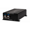
For remote control, there is by default an Ethernet/LAN port available on the front of the modules. Via this configurable connection users can completely control all functions of the modules either via SCPI language, ModBus RTU or ModBus TCP protocol.
An USB port, also located on the front side, is intended for USB sticks in order to load and save sequences for the sequence generator or load/save curve for MPP tracking.
For the implementation into the LabView IDE we offer ready-to-use components (VIs) to be used with the Ethernet interface. Other IDEs and interfaces are supported by documentation about the communication protocol.
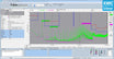
Windows users can profit from the free software “EA Pow-er Control”. It offers a feature called “Sequencing”, where the device is controlled through a table in CSV format to achieve automatic test runs. This table represents simple to complex test procedure and can be created and edited in MS Excel or other CSV editors and then imported into the software tool. This software also allows for the control of up to 20 units at once with an optional feature called “Multi Control” (licensed, not free of charge).
Sequence generator
A special feature is the digital sequence generator. It enables to control the load unit by semi-automatic sequence blocks (max. 100). Those blocks consist of programmable set val-ues for voltage, current and power, plus a time value. The generator can apply a rectangular wave signal to any or all set values at once.
Specifikationer
Dokumenter
Valgmuligheder
Video
This series EA-ELR 5000 was designed to configure a multi-channel electronic DC load. In a rack for 19” sys-tems, up to ten DC load units with 320 W nominal power each can be installed. The modular units operate separately from each other, but require the rack as it contains the energy recovering DC-AC inverter. The modules are also extendable. Parallel connection on the DC inputs of the module is possible. The load mod-ules come in two voltage variants, 80 V and 200 V, and incorporate the common regulation modes constant voltage (CV), constant current (CC) and constant power (CP).
The energy recovery function inverts the supplied DC energy into a synchronous sine current and feeds it back into the local grid. This reduces the usual heat dissipation to a minimum and saves energy costs at the same time. The color TFT touch panel offers an intuitive kind of manual operation.
Equipped with an Ethernet port by default, the load units can be easily integrated into a network of LAN devices with a standard LAN switch, which is also available as accessory (Netgear, 1U, 19”). External con-trol is possible via an included Windows software or via custom applications created in LabView or other IDEs. The commonly known communication protocols SCPI and ModBus RTU are supported.
* Modbus TCP only from firmware 2.05
Features:
- Multi-channel DC load
- Energy recovery of the supplied DC energy into the local grid
- 19” 6U rack for up to 10 separate load modules
- Input power rating: 320 W per module
- Input voltages: 80 V or 200 V
- Input currents: 12 A or 25 A per module
- Remote sensing
- μController based digital control
- Bilingual TFT touch panel (German/English)
- Sequence generator
- Battery test function
- MPP tracking function
- Ethernet/LAN interface built-in
- SCPI and ModBus RTU/TCP* command set
Power ratings, voltages, currents
There are two load models available. One for max. 80 V DC input voltage and one for max. 200 V. Both mod-els have a max. power of 320 W, while the 80 V model can take up to 25 A and the 200 V can take up to 12 A or current. By installing up to 10 units of these load modules into a single rack it's possible to extend the power to a total of 3200 W.
Construction
The rack, which is used to hold the load modules is designed in 19“ width and 6U of height, while having an installation depth of 480 mm (18.9”). This makes it ideal for use in 19“ cabinets of various sizes.
Supply
The rack requires to be wired to a main connection with 208 V AC (±10%) and minimum 16 A fusing. The re-covery feature requires to always have sufficient devices on the local power grid to consume the recuper-ated energy.
Energy recovery
The most important feature of these electronic loads is that the AC input, i.e. grid connection, is also used as output for the recov-ery of the supplied DC energy, which will be converted with an effi-ciency of up to 95%. This way of energy recovery helps to lower en-ergy costs and avoids expensive cooling systems, such as required for conventional electronic loads which convert the DC input ener-gy into heat.
Operation of these recovering loads in terms of electricity gener-ation is not intended. Grid protection devices which can supervise the feedback of energy into the public grid are available on the mar-ket for optional installation and are installed to achieve additional safety of persons and equipment, especially when running the so-called isolated operation.
Operation (HMI)
Manual operation is done with a resistive touch panel, two rotary knobs and a pushbutton. The color display shows all relevant set values and actual values at a glance. The whole setup is also done with the human-machine interface, as well the configuration of the sequence generator.
Remote control & connectivity
For remote control, there is by default an Ethernet/LAN port available on the front of the modules. Via this configurable connection users can completely control all functions of the modules either via SCPI language, ModBus RTU or ModBus TCP protocol.
An USB port, also located on the front side, is intended for USB sticks in order to load and save sequences for the sequence generator or load/save curve for MPP tracking.
For the implementation into the LabView IDE we offer ready-to-use components (VIs) to be used with the Ethernet interface. Other IDEs and interfaces are supported by documentation about the communication protocol.
Windows users can profit from the free software “EA Pow-er Control”. It offers a feature called “Sequencing”, where the device is controlled through a table in CSV format to achieve automatic test runs. This table represents simple to complex test procedure and can be created and edited in MS Excel or other CSV editors and then imported into the software tool. This software also allows for the control of up to 20 units at once with an optional feature called “Multi Control” (licensed, not free of charge).
Sequence generator
A special feature is the digital sequence generator. It enables to control the load unit by semi-automatic sequence blocks (max. 100). Those blocks consist of programmable set val-ues for voltage, current and power, plus a time value. The generator can apply a rectangular wave signal to any or all set values at once.